Microchip ATtiny Series Matching Data
◆ For customers considering Microchip ATtiny series.
SII lineup of compatible 32kHz crystal units and optimum circuit constants.
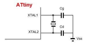
・Circuit Diagram

・Product and recommended circuit constants
| IC Type | Power System | 32kHz Crystal Unit | External Element | 32kHz specification | |||
| Size (mm) | Product Name | CL (pF) | Cg (pF) | Cd (pF) | |||
| ATtiny817 | 1V8 | 7.0 x 1.5x1.4 | SSP-T7-F | 7 | 9 | 9 | Click here for specifications |
| 2V7 | 7 | 9 | 9 | ||||
| 3V3 | 7 | 9 | 9 | ||||
| 5V5 | 7 | 9 | 9 | ||||
| 1V8 | 3.2×1.5×0.85 | SC-32S | 7 | 9 | 9 | Click here for specifications | |
| 2V7 | 7 | 9 | 9 | ||||
| 3V3 | 7 | 9 | 9 | ||||
| 5V5 | 7 | 9 | 9 | ||||
| 1V8 | 2.0×1.2×0.60 | SC-20S | 7 | 9 | 9 | Click here for specifications | |
| 2V7 | 7 | 9 | 9 | ||||
| 3V3 | 7 | 9 | 9 | ||||
| 5V5 | 7 | 10 | 10 | ||||
| 1V8 | 1.2×1.0x0.50 | SC-12S | 7 | 9 | 9 | Click here for specifications | |
| 2V7 | 7 | 9 | 9 | ||||
| 3V3 | 7 | 9 | 9 | ||||
| 5V5 | 7 | 9 | 9 | ||||
| ATtiny85 | 2V7 | 7.0 x 1.5x1.4 | SSP-T7-F | 7 | 6 | 6 | Click here for specifications |
| 3V3 | 7 | 4 | 4 | ||||
| 5V5 | 7 | 4 | 4 | ||||
| 2V7 | 3.2×1.5×0.85 | SC-32S | 7 | 4 | 4 | Click here for specifications | |
| 3V3 | 7 | 2 | 2 | ||||
| 5V5 | 7 | 2 | 2 | ||||
| 2V7 | 2.0×1.2×0.60 | SC-20S | 7 | 3 | 3 | Click here for specifications | |
| 3V3 | 7 | 1 | 1 | ||||
| 5V5 | 7 | 1 | 1 | ||||
| 2V7 | 1.2×1.0x0.50 | SC-12S | 7 | 2 | 2 | Click here for specifications | |
| 3V3 | 7 | 3 | 3 | ||||
| 5V5 | 7 | 5 | 5 | ||||
For detailed data, please see here. ☞ Detailed Data
For other products, please contact us. ☞ Contact Us
◆Circuit board design considerations
Place the crystal unit, capacitors, and resistors as close to the Chip as possible to shorten the wiring.
To prevent interference with other signal lines, do not place other signal lines in the area where the crystal unit is mounted (underside).
For more information on oscillation circuit design, please refer to the following link.
Learn more about oscillation circuit design
We recommend that you check with your actual board, so please use our circuit matching service.
For details, please contact our sales representatives or click the link below.
◆Caution
The above evaluation results are reference values evaluated on specific samples and “IC manufacturer’s evaluation board”.
They are subject to change depending on the customer’s board design.
Please note that the capacitance values and characteristics of the attached elements may vary depending on the stray capacitance and other factors on the actual circuit board.