Quartz

Quartz

Overview of 32kHz Oscillator Circuit Design

Key Parameters for 32kHz Oscillator Circuit Design

DRIVE LEVEL (DL), OSCILLATION FREQUENCY AND LOAD CAPACITANCE (CL), OSCILLATION ALLOWANCE, FREQUENCY-TEMPERATURE CURVE

DRIVE LEVEL (DL)

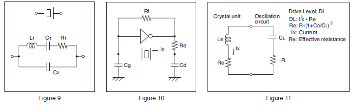
The drive level of a crystal unit is shown by the level of the operating power or the current consumption (see Figures 9,10, and 11). Operating the crystal unit at an excessive power level will result in the degradation of its characteristics, which may cause frequency instability or physical failure of the crystal chip. Design your circuit within absolute maximum drive level.

Technical diagrams of crystal unit characteristics. Figure 9 shows the electrical equivalent circuit. Figure 10 illustrates a standard oscillation circuit using an inverter and resistors. Figure 11 presents the model for calculating drive level based on current and resistance. These diagrams emphasize the importance of proper circuit design to ensure component reliability

OSCILLATION FREQUENCY AND LOAD CAPACITANCE (CL)

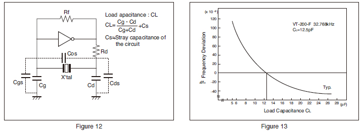
The load capacitance (CL) is a parameter for determining the frequency of the oscillation circuit. The CL is represented by an effective equivalent capacitance that is loaded from the oscillation circuit to both ends of the crystal unit (see Figure 12).
The oscillation frequency varies depending upon the load capacitance of the oscillation circuit. In order to obtain the desirable frequency accuracy, matching between the load capacitances of the oscillation circuit and the crystal unit is required. For the use of the crystal unit, match the load capacitances of the oscillation circuit with the load capacitances of the crystal unit.

Technical diagrams regarding load capacitance (CL). Figure 12 shows an oscillation circuit and explains how to calculate CL, including the effect of stray capacitance. Figure 13 presents a graph showing that frequency deviation changes depending on the load capacitance value. The diagrams highlight that matching the circuit's CL with the crystal unit is essential for frequency accuracy

OSCILLATION ALLOWANCE

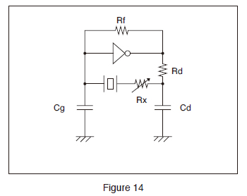
Technical diagram of an oscillation circuit (Figure 14) used for evaluating oscillation allowance. It shows a crystal unit connected in series with a variable resistor (Rx), alongside an inverter, feedback resistor, and load capacitors. This setup is used to determine the circuit's negative resistance by adjusting Rx

To ensure stable oscillation, the negative resistance of the circuit should be significantly larger than the equivalent series resistance (the oscillation allowance is large). Ensure that the oscillation allowance is at least five times as large as the equivalent series resistance.


Oscillation Allowance Evaluation Method 
Add resistor “Rx” to the crystal unit in series and ensure that the oscillation starts or stops. The approximate negative resistance of the circuit is the value obtained by adding the effective resistance “Re” to the maximum resistance “Rx” when the oscillation starts or stops after gradually making Rx value larger.

Negative resistance |- R| = Rx + Re

|−R| is a value at least five times as large as the maximum equivalent series resistance (R1 max.) of the crystal unit.
*Re is the effective resistance value during oscillation.
Re = R1 (1 + CO/CL 2

FREQUENCY-TEMPERATURE CURVE

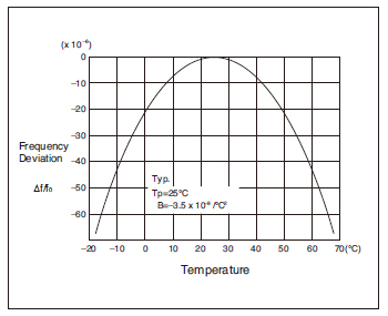
A technical graph showing the frequency temperature characteristics of a tuning fork crystal. The curve forms a negative parabola with its peak (zero deviation) at 25°C. It illustrates how frequency deviation increases as the temperature moves away from the turnover point

Frequency temperature characteristics of tuning fork crystals is shown by negative quadratic curve which has a peak at 25ºC as per left graph.
Please make sure to consider the temperature range and frequency accuracy you need since magnitude of frequency variation becomes larger and larger as the temperature range becomes wider.

[Approximation formula of frequency temperature characteristics]
f_tem = B(T-Ti) 
B : Parabolic coefficient
T : Given temperature
Ti : Turnover temperature

Click here and jump to “IC matching results with semiconductor manufacturers”.